Bias Tees
Broadband RF Bias Tees
High-performance bias tees for broadband RF and microwave applications from Hz to 40 GHz, with options for high power, high current and custom electrical requirements.
RF Bias Tees Designed for Demanding Applications
Taylor Microwave bias tees combine broadband RF performance with DC injection and isolation in a compact package. Standard, high-power and high-current configurations are available, with custom designs developed for specific frequency, voltage, current and power requirements.
Choose the Right Bias Tee
Standard Bias Tees
Broadband models for general RF and microwave applications.
High Power
Bias tees designed for higher RF power levels and demanding thermal environments.
High Current
Low-frequency bias injection combined with high DC current capability.
Custom Designs
Custom frequency, voltage, current, power and connector configurations.
New Compact Bias Tee
| Model | (1) Frequency Range | Insertion Loss (dB Max.) | (2) Isolation (dB Min.) | VSWR (Max.) | (3) Input Power (dBm Max.) | (4) DC Current Amps Max. | (5) Bias Voltage Vdc Max. | (6) Bias Frequency Bandwidth |
|---|---|---|---|---|---|---|---|---|
| BT-A1 | 250KHz to 27 GHz | 1.50 | 60** | 1.7:1 | + 40.00 (10W CW)** | 20 | 50 | |
| BT-A2 | 250KHz to 40 GHz | 2.50 | 40** | 1.8:1 | + 40.00 (10W CW)** | 20 | 50 | |
| BT-A3 | 15MHz to 20 GHz | 1.50 | 50** | 2:1 | + 44.80 (30W CW)** | 20 | 50 |
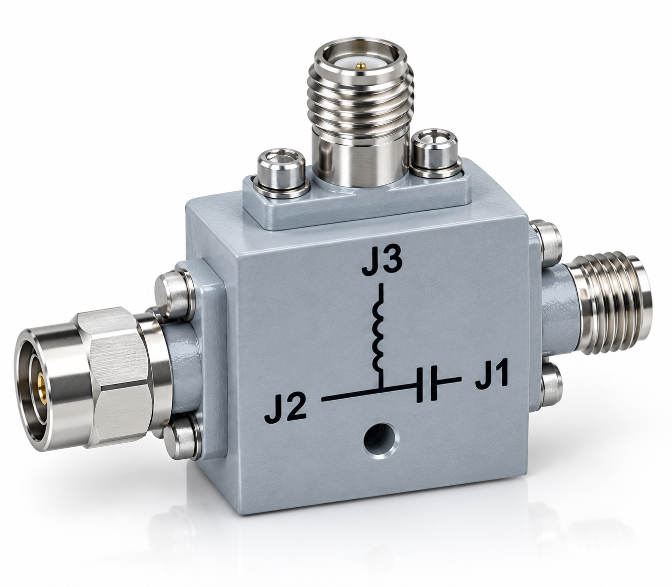
Standard Bias Tee Specifications
| Model No. | (1) Frequency Range | Insertion Loss (dB Max.) | (2) Isolation (dB Min.) | VSWR (Max.) | (3) Input Power (dBm Max.) | (4) DC Current ma Max. | (5) Bias Voltage Vdc Max. | (6) Bias Frequency Bandwidth |
|---|---|---|---|---|---|---|---|---|
| BT-A01 | 10 MHz to 3 GHz | 0.50 | 40 | 1.2:1 | +30.0 | 500 | 50 | |
| BT-A02 | 10 MHz to 8 GHz | 1.0 | 30 | 1.3:1 | +30.0 | 500 | 50 | |
| BT-A03 | 100 MHz to 18 GHz | 1.25 | 30 | 1.3:1 | +30.0 | 500 | 50 | |
| BT-A04 | 500 MHz to 4 GHz | 0.50 | 30 | 1.3:1 | +30.0 | 500 | 50 | |
| BT-A05 | 1 GHz TO 8 GHz | 1.0 | 30 | 1.3:1 | +30.0 | 3000 | 50 | |
| BT-A06 | 10 KHz to 20 GHz | 1.1 | 40 | 1.5:1 | +33.0/+40.00 (see drawing) | 500 | 50 | |
| BT-A07 | 100 KHz to 4 GHz | 1.0 | 40 | 1.5:1 | +40.0 | 1000 | 50 | |
| BT-A08 | 30 KHz to 30 GHz | 1.75 | 30 | 1.8:1 | +30.0 | 750 | 25 | |
| BT-A09 | 500 MHz to 12 GHz | 2.0 | 30 | 2:1 | +30.0 | 20 | 2000 | |
| BT-A10 | 500 MHz to 3 GHz | 0.50 | 30 | 1.5:1 | +40.0 | 10000 | 50 | |
| BT-A11 | 500 Hz to 10 GHz | 1.5 | 18 | 2:1 | +30.0 | 250 | 50 | |
| BT-A12 | 10 MHz to 18 GHz | 1.25 | 25 | 2:1 | +40.0 | 750 | 50 | |
| BT-A13 | 500Hz to 500 MHz | 1.0 | 20 | 1.5:1 | +40.0 | 250 | 50 | |
| BT-A14 | 500MHz to 25 GHz | 1.25 | 40 | 1.5:1 | +37.0 | 2000 | 100 | 2 MHz |
| BT-H01 | 500KHz to 12 GHz | 2.25 | 30 | 2:1 | +44.8 | 2500 | 250 | |
| BT-GA01 | 25KHz to 40 GHz | 1.75 | 40 | 1.7:1 | +40.0 | 750 | 50 | |
| BT-GA02 | 125KHz to 40 GHz | 1.75 | 40 | 1.7:1 | +40.0 | 2000 | 50 |
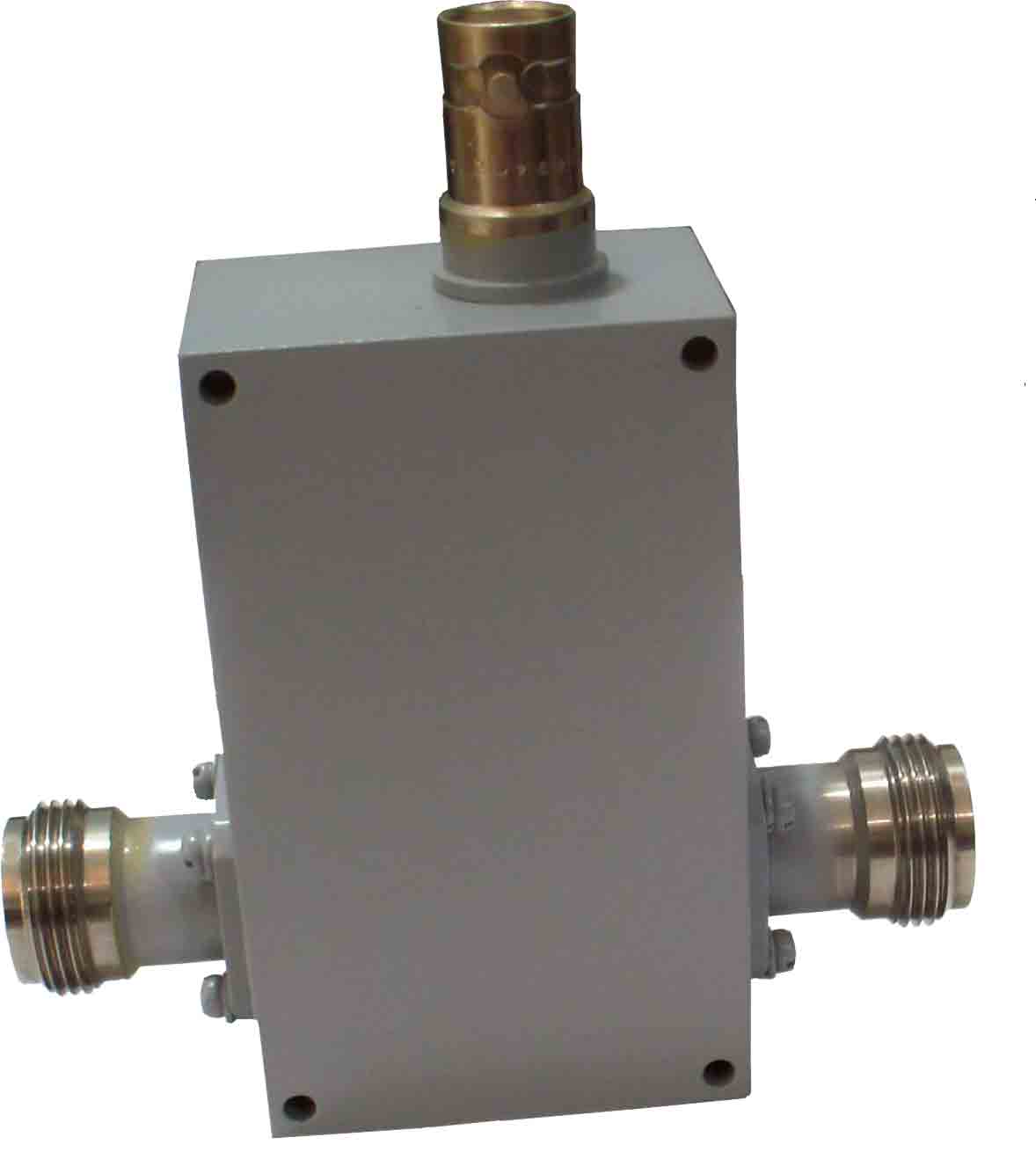
High Power Bias Tees
High-power models are designed for RF systems requiring increased RF power handling while maintaining reliable DC injection and broadband performance.
| Model No. | (1) Frequency Range | Insertion Loss (dB Max.) | (2) Isolation (dB Min.) | VSWR (Max.) | (3) Input Power (dBm Max.) | (4) DC Current ma Max. | (5) Bias Voltage Vdc Max. | (6) Bias Frequency Bandwidth |
|---|---|---|---|---|---|---|---|---|
| BT-H02 | 0.50 to 6 GHz | 0.75 | 50 | 1.3:1 | + 50.00 (100W CW) | 7000 | 250 | |
| BT-H03 | 0.50 to 18 GHz | 2.0 | 50 | 1.5:1 | + 46.00 (40 WCW) | 2000 | 250 | |
| BT-H04 | 1MHz to 7 GHz | 1.0 | 50 | 1.4:1 | + 50.00 (100 WCW)** | 5000 | 250 | |
| BT-H06 | 10 MHz to 18 GHz | 2.0 | 50 | 2.0:1 | + 47.00 (50 WCW)** | 2000 | 250 |
High Current Bias Tee
Low-frequency bias injection combined with high DC current capability. Up to 30 A available| Model | (1) Frequency Range | Insertion Loss (dB Max.) | (2) Isolation (dB Min.) | VSWR (Max.) | (3) Input Power (dBm Max.) | (4) DC Current Amps Max. | (5) Bias Voltage Vdc Max. | (6) Bias Frequency Bandwidth |
|---|---|---|---|---|---|---|---|---|
| BT-HC01 | 100KHz to 2 GHz | 1.75 | 50 | 1.5:1 | + 40.00 (10W CW) | 20 | 50 | DC to 1KHz |
| BT-HC01-L | 3MHz to 2 GHz | 2.00 | 50 | 1.5:1 | + 40.00 (10W CW)* | 20 | 50 | DC to 30KHz |
Engineering Features
Broadband Performance
Models are available from low-frequency bias applications through microwave frequencies extending to 40 GHz.
High Isolation
High-isolation configurations are available for applications where RF energy must be isolated from the DC source.
High RF Power
High-power versions are available for applications requiring up to 200 W CW RF power.
High DC Current
High-current designs are available with DC current ratings up to 20 A.
Multiple Connectors
SMA, N, TNC and BNC connector configurations are available.
Custom Engineering
Taylor Microwave can develop custom bias tees for specific frequency, voltage, current, power and mechanical requirements.
Need a Custom Bias Tee?
Our engineering team can design a bias tee around your specific RF and DC requirements.
- Custom frequency range
- High RF power handling
- High DC current
- High bias voltage
- Low insertion loss
- High RF-to-DC isolation
- Custom SMA, N, TNC or BNC connectors
- Custom mechanical package
General Specifications
- Bandwidth options are available up to 40 GHz.
- Higher isolation is available on selected models.
- RF power ratings can be increased for custom designs.
- DC current ratings up to 35 A are available.
- Nominal impedance: 50 Ω.
- Typical operating temperature range: −55°C to +85°C.
- Custom designs are available.
Tell Us What You Need
If you need a bias tee that doesn’t fit one of our standard configurations, contact Taylor Microwave. We can develop a solution around your RF frequency, power, current and voltage requirements.
Get a Product Quote